Moverio BT-350 / 3D mode / Unity
1. SDK Version: 4.1.0
2. Development Environment: Unity-Android
3. Tracker/Scanner: // n.a.
4. License Type: Free
5. Target Device(Optional): Epson Moverio BT350
I have done calibration multiple times, using your calibration app, and it seems fine when testing the image frame, however, when I switch to the Unity samples, and I use de 3D mode (ohmd stereo mode), the display doesn't seem to match the target marker.
The augmented model usually appears to the left of the target and "out of focus" (the vergence distance does not match the real world distance to the target marker).
Could you provide some insight as to why this happens?
I've managed to alleviate the problem at a fixed distance by tweaking the positions of the left and right eye camera gameobjects but I can't achieve the same result as in the calibration app view mode.
Thank you kindly for your attention.
The Unity sample app you downloaded has an image tracker example. There are three ImageTrackable objects. Each Image Trackable object has an image map to track and content to augment when tracking succeeds. We have learned the actual size of the image map provided by the sample as 0.26m. The size of the image is full, except for the margin of 0.01m on the A4 paper. We calculate the position of the content to be augmented using the information center, ie, the size of the learned image is 0.26 m. However, if you look at what you see from the left side of the content, it is likely that the size of the image you are actually looking at is different.
As a result, the actual image size - the learned image map (.2dmap) must match to float to the correct location.
There are two solutions you can do. The first is to print the image full on A4 paper. The second is to look at our image tracking example and create a new image map (.2dmap) for the size of the image you have. Choose one of the methods that I have suggested.
Good luck.
Leo
Maxst Support Team
Thank you for the prompt answer. I did not make the question explicit enough but you might have hinted at the root of the problem.
The problem is related to the MarkerTracker sample.
I can't take a screen of what exactly I see through the glasses but hopefully, the following image will clarify what the problem is.
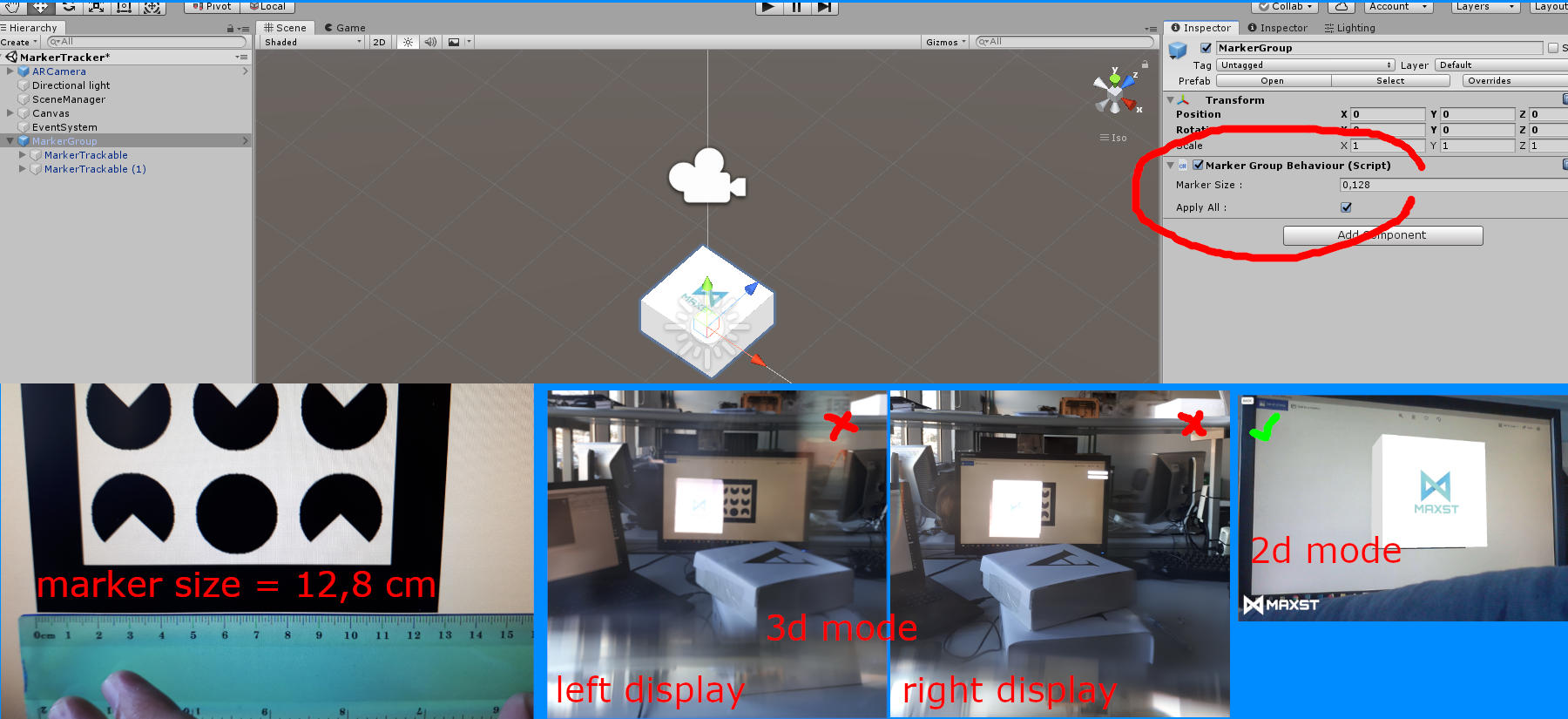
I have also tried with a 9cm marker and tried attributing different values to the Marker Size param but it does not seem to make a difference.
I was expecting the model to follow the marker accurately as was the case with the calibration examples. I did the calibration with a printed image from the calibration pdf document and its dimensions on the paper are 0.248m x 0.175m ~~. It is possible that the dimensions are wrong... was it supposed to be 0.26m wide picture? (meanwhile, I will try to calibrate with a 0.26m wide picture and see if it solves the problem)
Calibration Calibrate near, medium, and long distances in the app. The three corrected distances are about 0.8m 1.0m and 1.2m when I experiment. In the corrected distance, the position to be augmented and the size of the cube are corrected to some extent to improve the error, but it seems that an error occurs at a closer distance than the corrected distance.
And when we asked your question directly, we started changing the parameter to JSON in the marker tracker when we released version 4.1.0, but it did not reflect the code and document. The code changed to JSON format will be released in 4.1.1, and if you want to test first, you can modify it in the following two .cs code.
MarkerGroupBehaviour.cs
if (applyAll)
{
TrackerManager.GetInstance (). AddTrackerData ("{\" marker \ ": \" scale \ ", \" all \ ":" + markerGroupSize + "}");
}
else
{
TrackerManager.GetInstance (). AddTrackerData ("{\" marker \ ": \" scale \ ", \" all \ ":" + defaultSize + "}");
}
MarkerTrackerBehaviour.cs
public void SetMarkerTrackerFileName (int id, float size) {
// string temp = "id" + id.ToString () + ":" + size.ToString ();
// Debug.Log ("0:" + temp);
// temp = ":" + size.ToString ();
// Debug.Log ("1:" + temp);
TrackerDataFileName = "{\" marker \ ": \" scale \ ", \" id \ "" + id + ":" + size + "}";
Debug.Log (TrackerDataFileName);
}
In Unity, it is the code that puts the marker size set in the properties of MarkerGroup and MarkerTrackable into JSON format and passes it as parameter.
I have just modified the document. It is thanks to you.
https://developer.maxst.com/MD/doc/4_1_x/unity/ex/marker
Please refer to the above page for setting the marker size in Unity.
If you want to get a more accurate result without any error, we recommend writing a larger image of the output marker image, or selecting Extended Tracking mode in the marker tracker and tracking it over a long distance.
Good luck to you!
Leo
Maxst Support Team
Thank you. This solved the problem.
You're welcome. good luck.
Leo
Maxst Support Team